
Selecting the Right Hydraulic Flow Divider: A Comprehensive Guide
2025-04-24Choosing the right components is crucial for any hydraulic system's performance and longevity. Among these, the hydraulic flow divider plays a vital role in distributing fluid flow accurately. But how do you select the best flow divider for your specific needs? Getting this choice right ensures your machinery operates smoothly, synchronizes actuators effectively, and avoids costly inefficiencies or failures. This article dives deep into the world of hydraulic flow dividers, exploring the different types (gear vs. spool), key selection factors, common pitfalls, and expert insights to help you make an informed decision. Whether you're a machinery manufacturer like many of our clients in the USA and Europe, or a system integrator, understanding the nuances of flow divider selection is essential for optimal hydraulic system function. Read on to ensure you're selecting the right hydraulic flow divider for your application.
What Exactly is a Hydraulic Flow Divider Used For?
At its core, a hydraulic flow divider is a specialized valve assembly designed to take a single input hydraulic flow and split it into two or more output flows. The primary use of a flow divider is often to synchronize the movement of multiple hydraulic cylinders or motors. Imagine needing two cylinders to extend at precisely the same rate, even if they encounter slightly different load conditions. A flow divider helps achieve this by ensuring each actuator receives a predetermined portion of the total flow.
Beyond synchronization, flow dividers are also used to provide proportional flow to different parts of a hydraulic circuit. For instance, one output might power a primary function, while a second, smaller flow powers an auxiliary function. This capability is invaluable in complex machinery, especially in mobile hydraulic applications like construction equipment, agricultural machinery, and material handling systems where multiple functions often operate simultaneously. The ability of a flow divider to manage flow distribution allows for more sophisticated and efficient machine designs. We often see the use of a flow divider in equipment needing balanced operation, like lifting platforms or complex grapples.
Gear Flow Divider vs. Spool Flow Divider: What's the Difference?
When you need to split hydraulic flow, two main types of flow dividers are commonly available: gear flow dividers and spool type flow dividers. Understanding their fundamental differences is the first step in making the right choice for your project.
A gear flow divider operates on the principle of positive displacement. It essentially consists of two or more internally coupled gear sections housed within a single body. Hydraulic fluid enters the flow divider and forces the gears to rotate. Because the gear sections are mechanically linked (usually by a common shaft), they rotate at the same speed. Each gear section has a specific displacement (volume of fluid moved per rotation). If the gear sections have equal displacements, the flow divider splits the input flow equally among the outputs. Unequal displacements result in a proportional flow split according to the gear ratio. This positive displacement nature generally leads to higher precision in flow division, especially when output pressures are relatively balanced. The gear type flow divider is often the preferred choice for applications demanding accurate synchronization.
A spool type flow divider, on the other hand, works more like a pressure-compensated proportional valve. It typically uses internal orifices and a sliding spool mechanism. The spool shifts based on pressure differences between the output lines, attempting to adjust the orifice sizes to maintain the desired flow ratio. While simpler in construction and often less expensive than gear dividers, their accuracy is much more sensitive to variations in downstream pressure and load. A significant pressure differential between the outputs can cause the spool to shift fully, potentially leading to a situation where the flow division capability disappears entirely on one side. While a spool type flow divider might seem like a good way to save money and space, its limitations must be carefully considered. It's often considered less tolerant of contamination compared to a gear flow divider.
Here's a quick comparison:
| Feature | Gear Flow Divider | Spool Type Flow Divider |
|---|---|---|
| Operating Principle | Positive Displacement (Gears) | Orifice / Pressure Compensation (Spool) |
| Accuracy | Generally High, less affected by pressure | Lower, highly affected by pressure |
| Synchronization | Excellent under balanced loads | Fair, degrades with pressure imbalance |
| Cost | Generally Higher | Generally Lower (less expensive) |
| Complexity | More complex internal parts | Simpler construction |
| Contamination | Moderately tolerant | Can be less tolerant |
| Heat Generation | Lower (more efficient) | Higher (due to throttling) |
| Size/Weight | Can be larger/heavier | Often more compact |
How Does a Gear Flow Divider Achieve Precision Flow Division?
The magic behind the precision of a gear flow divider lies in its positive displacement mechanics. Think of it like two (or more) perfectly matched hydraulic motors sharing the same input source and mechanically linked by a shaft. As incoming oil pushes against the gear teeth, it forces the gear sets to rotate. Since they are linked, they must rotate at the same speed.
Each rotation of a gear section displaces a fixed volume of oil. If the gear sections are manufactured with identical displacement volumes (for a 50/50 split), then each output port will deliver virtually the same amount of flow per unit of time, assuming the gears turn at the same speed. This mechanical coupling is what provides the inherent precision of the gear flow divider. Minor variations in manufacturing tolerances are the primary source of any built-in inaccuracy, but modern manufacturing techniques keep these extremely tight. The result is a highly reliable method for achieving accurate flow division. This precision is critical in applications like synchronized lifting systems.
However, no mechanical system is perfect. The main factor affecting the real-world precision of a gear flow divider is internal leakage, also known as slip. This is the small amount of oil that bypasses the gear teeth due to internal clearances between the gears and the housing. This leakage increases as the pressure differential between the output ports increases, or as the hydraulic fluid viscosity decreases (e.g., at higher temperatures). So, while a gear flow divider offers excellent precision under ideal conditions (balanced loads, stable temperature), its accuracy can slightly degrade under high differential pressure situations. Despite this, the gear type is often considered the best performing type of flow divider for precision tasks.
When Should You Use a Spool Type Flow Divider?
While gear flow dividers excel in precision, there are scenarios where a spool type flow divider presents a viable, and sometimes preferable, alternative. The primary drivers for choosing a spool type are often cost and size. They tend to be less expensive and more compact than their gear counterparts, which can be significant advantages in cost-sensitive projects or space-constrained mobile applications. If your application requires only approximate flow division and doesn't involve synchronizing actuators under significantly varying loads, a spool type flow divider might be an acceptable solution.
However, it's crucial to be fully aware of the disadvantages of a spool type flow divider. Their accuracy is highly dependent on the pressure at the outlet ports. If one output line sees a significantly higher pressure (e.g., one cylinder hits its end-of-stroke before the other, or encounters a heavier load), the internal spool will shift to restrict flow to the lower-pressure side and open flow to the higher-pressure side. In extreme cases, if one outlet is completely blocked or sees very low pressure, the flow division capability disappears and the spool type flow divider might as well not be there for that leg – nearly all flow will divert to the path of least resistance. This can lead to jerky, unsynchronized movement and potential system issues. Furthermore, the throttling action inherent in spool dividers creates heat, reducing overall hydraulic system efficiency. You might think you can save money and space by using a spool type flow divider, but if the application requires synchronization under varying loads, you could be setting yourself up for failure. Careful consideration must be given; unless cost or weight are prohibitive, a gear flow divider is usually the safer bet for synchronization.
What Key Factors Must I Consider to Select the Right Hydraulic Flow Divider?
Making the optimal selection involves evaluating several key parameters of your hydraulic system and application requirements. Getting this selection process right ensures the flow divider performs as expected without causing issues downstream. Here’s a checklist of factors to consider:
- Input Flow Rate: The flow divider must be rated to handle the maximum flow supplied by the pump to its inlet port. Operating a flow divider above its rated flow can cause excessive pressure drop, heat generation, and potential damage.
- Operating Pressure: Ensure the flow divider's maximum pressure rating exceeds the maximum expected working pressure of your hydraulic system, including any potential pressure spikes. This applies to both inlet and outlet ports.
- Number of Sections: How many ways does the flow need to be split? Standard flow dividers typically come in 2, 3, or 4 sections, but custom configurations are possible. This determines how many actuators or sub-circuits can be powered. For example, synchronizing 2 cylinders requires a 2-section flow divider.
- Division Ratio: Do you need an equal split (e.g., 50/50 for 2 sections) or an unequal, proportional split (e.g., 60/40)? For gear flow dividers, this is determined by the relative displacement of the gear sections. Specify the required ratio based on the needs of the actuators being supplied.
- Required Precision: How accurately do the output flows need to match the specified ratio? For critical synchronization tasks (e.g., lifting platforms, precision mobile equipment), a high-precision gear flow divider is usually necessary. For less critical applications where only approximate division is needed, a spool type flow divider might suffice, bearing in mind its limitations under differential pressure. Define the acceptable accuracy tolerance for your project.
- Fluid Type and Viscosity: Ensure the flow divider's seals and materials are compatible with the hydraulic fluid being used. Viscosity affects internal leakage (especially in gear dividers) and pressure drop, so consider the operating temperature range.
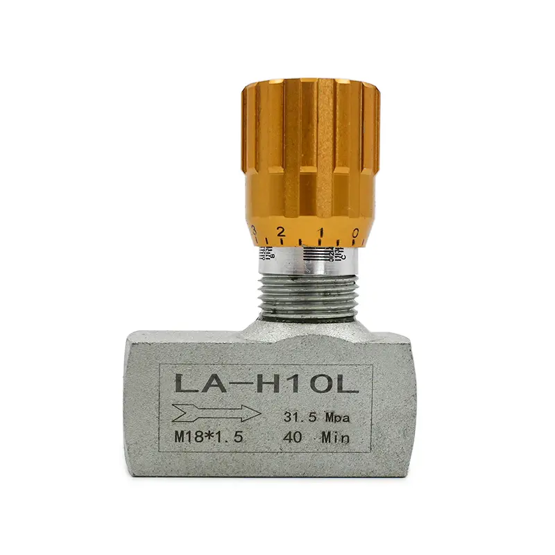
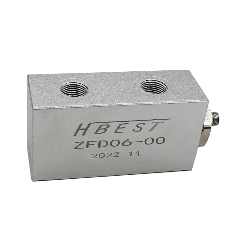
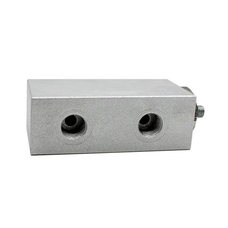
- Mounting and Porting (Fitting): How will the flow divider be integrated into the system? Consider the required port types and sizes (e.g., SAE, BSPP, NPTF) and the physical mounting configuration (inline, manifold mount). Ensure proper fitting integration. The physical dimension and fitting options are important practical considerations.
- Application Environment: Factors like ambient temperature, potential for contamination, and vibration levels in mobile or industry settings can influence the choice of materials, seals, and overall robustness needed for the flow divider product.
How Do Pressure Variations Affect Flow Divider Performance?
Pressure variations between the outlet ports of a flow divider are a critical factor influencing performance, particularly accuracy. The two main types react differently.
For a gear flow divider, the impact of differential pressure primarily relates to internal leakage or slip. As the pressure difference between two output sections increases, more hydraulic fluid tends to leak past the internal seals and gear clearances from the high-pressure side back towards the lower-pressure side or the inlet. This means the section feeding the higher pressure load receives slightly less flow than intended, and the section feeding the lower pressure load receives slightly more. While the mechanical link forces the gears to turn at the same speed, the effective displacement is slightly altered by this leakage. Therefore, the accuracy of a gear flow divider decreases as the differential pressure increases. However, this effect is generally predictable and relatively small compared to spool dividers, especially in well-manufactured units. The precision is affected by pressure, but often remains within acceptable limits for many synchronization tasks.
Spool type flow dividers are far more sensitive to pressure variations. Their operation relies on the spool dynamically adjusting orifice sizes based on pressure feedback. When outlet pressures are equal, the spool stays centered, and flow is divided according to the fixed orifice sizes. However, if one outlet pressure rises significantly above the other, the pressure imbalance pushes the spool, restricting the orifice leading to the lower-pressure port and opening the orifice to the higher-pressure port. This is the pressure compensation mechanism attempting to maintain flow proportion. But if the pressure difference becomes too large, the spool can shift completely, drastically altering the flow split. In the worst-case scenario (e.g., one outlet blocked), the flow division capability disappears for the low-pressure side, with almost all flow going to the path of least resistance. This makes spool dividers unsuitable for applications requiring consistent synchronization under varying load conditions.
Can I Use Valves with a Flow Divider?
Yes, other hydraulic valves can certainly be used in conjunction with a flow divider, but their type and placement within the circuit require careful consideration to avoid negatively impacting the divider's function and accuracy. Common valves used include relief valves, check valves, flow control valves, and counterbalance valves.
The primary concern is how these valves might create or exacerbate pressure differences between the flow divider's outlet ports. For instance, placing individual relief valves directly on each outlet line of a flow divider can be problematic. If one relief valve opens while the other remains closed, it creates a significant pressure imbalance across the flow divider. As discussed, this degrades the accuracy of a gear flow divider and can completely disrupt the function of a spool type flow divider. A better approach is often to place a single relief valve before the flow divider inlet to protect the entire circuit.
Similarly, using meter-out flow control valves or certain types of load-holding valves (like standard pilot-operated check valves or Direct Acting Sequence Valves) downstream of the divider can create back pressure and differential pressure issues. If precise synchronization is critical, especially when using a gear flow divider, it's often best to control flow before the divider or use specialized valve arrangements. Using counterbalance valves or placing the divider and associated valves strategically is key. Sometimes, integrating the load control function within the flow divider assembly itself (using specialized cartridge valve designs) is the most effective solution. Always analyze the potential pressure conditions created by downstream valves and their impact on the flow divider's performance.
How Do I Size a Flow Divider Correctly for My Hydraulic System?
Correctly sizing a flow divider is essential for proper function and efficiency. Undersizing can lead to excessive pressure drop and heat, while gross oversizing might not be cost-effective and could potentially affect low-flow accuracy. The process involves matching the flow divider's specifications to the hydraulic system's requirements.
First, determine the total input flow rate that will be supplied to the flow divider under normal operating conditions. This is typically dictated by the pump output allocated to that part of the circuit. Ensure the flow divider's rated input flow capacity meets or slightly exceeds this value.
Second, establish the required output flow(s) or the division ratio. If you need to synchronize two identical cylinders, you'll likely need a 50/50 split from a 2-section flow divider. If you need to power two different functions with different flow requirements, specify the desired percentage or flow rate for each output. For gear flow dividers, this translates to selecting a unit with the appropriate displacement for each gear section. For example, a 50/50 divider might have two sections of 5cc/rev displacement, while a 60/40 divider might have sections of 6cc/rev and 4cc/rev.
Third, confirm the maximum operating pressure. The selected flow divider must have a pressure rating suitable for the maximum system pressure it will encounter. Finally, consult the manufacturer's technical data sheets. These provide detailed performance curves showing pressure drop versus flow rate, accuracy specifications under different differential pressure conditions, displacement figures, port size options (fitting details), and dimensional information. Using this data ensures the selected flow divider size and type align perfectly with your hydraulic system's demands. Don't hesitate to consult with the manufacturer's technical support if you're unsure about the optimal size a flow divider for your specific application.
What Are Common Problems with Hydraulic Flow Dividers and How to Avoid Them?
Even with careful selection, issues can arise with hydraulic flow dividers during operation. Understanding common problems helps in troubleshooting and prevention.
- Inaccurate Flow Division: This is perhaps the most common complaint.
- Causes: Excessive wear (especially in gear dividers), operating outside specified pressure/flow limits, high differential pressure (especially impacts spool dividers), contaminated oil causing wear or sticking (spool dividers), incorrect initial selection (using a spool type flow divider for a high-precision task).
- Prevention/Solution: Select the appropriate type (gear for precision), operate within specs, maintain clean hydraulic fluid, filter properly, address causes of high differential pressure (e.g., mismatched loads, downstream restrictions), perform regular maintenance checks.
- Excessive Heat Generation: Noticeable temperature increase around the flow divider.
- Causes: Primarily an issue with spool type dividers due to inherent throttling losses (inefficiency creates heat), operating above rated flow (high pressure drop), internal friction/wear. Gear dividers are generally more efficient and generate less heat unless significantly worn or operated improperly. Flow dividers aren’t creating heat if they aren’t working hard or inefficiently.
- Prevention/Solution: Ensure correct sizing, use a gear flow divider for efficiency if heat is a concern, ensure adequate system cooling, check for excessive pressure drop.
- Noise or Cavitation: Whining, grinding, or rattling sounds.
- Causes: Air in the hydraulic system, insufficient inlet pressure (cavitation), misalignment, internal wear/damage.
- Prevention/Solution: Bleed air from the system, ensure adequate charge pressure at the inlet (check pump/reservoir design), verify alignment, inspect for wear if noise persists.
- One Circuit Stops Working (Runaway): Especially noticeable with spool dividers under load imbalance.
- Causes: Extreme pressure differential causing the spool to fully shift, blocking flow to one outlet (a potential runaway meter-in situation). Blockage downstream of one outlet.
- Prevention/Solution: Avoid using spool dividers for critical synchronization under potentially high load variance. Use a gear flow divider instead. Check for downstream blockages or failed components (e.g., seized cylinder).
Regular system monitoring and preventative maintenance are key to avoiding these problems and ensuring the long life and reliability of your hydraulic flow divider. Signing up for a manufacturer's newsletter can also provide useful maintenance tips.
Why Partner with a Reliable Hydraulic Flow Divider Manufacturer for Your Industry Needs?
As someone who runs a factory producing hydraulic valves, including various types of flow dividers, I, Allen, understand the critical importance of component quality and reliability. For buyers like Mark Thompson in the USA, who source components for machinery manufacturers and hydraulic system integrators, partnering with the right supplier is paramount. The flow divider, especially the precision-engineered gear type, is not a component where corners should be cut in half.
Choosing a reputable manufacturer ensures:
- Consistent Quality: We utilize high-quality materials and maintain strict quality control across our 7 production lines. Every flow divider undergoes rigorous testing to meet performance specifications and international standards (like ISO). This minimizes the risk of premature failure and ensures reliable operation in demanding industry applications, from construction equipment to industrial machinery.
- Engineering Expertise: Selecting the correct flow divider type and size requires understanding the nuances of your application. A good manufacturer provides technical support to help you choose the best for my machine, considering factors like pressure, flow, precision, and integration with other hydraulic components like pressure control valves. We can help analyze if the advantages are more valuable than the disadvantages for a specific type in your project.
- Reliable Supply Chain: We know that shipment delays can disrupt production schedules – a major pain point for procurement officers. As an experienced exporter to the USA, North America, Europe, and Australia, we have robust logistics processes to ensure timely delivery. Direct communication with the factory eliminates layers of inefficiency.
- Trust and Transparency: Concerns about fraudulent certifications are valid. Working directly with an established factory provides greater transparency regarding testing, certifications, and manufacturing processes. We stand behind our products. You might even benefit from using a compact cartridge style flow divider integrated into a manifold, something we can discuss for your specific equipment.
Ultimately, while competitive pricing is important, the true cost includes reliability, performance, and the support you receive. Partnering with a dedicated manufacturer like ours provides peace of mind and ensures your hydraulic systems perform optimally. Don't hesitate to reach out to discuss your flow divider needs – and perhaps sign up for our newsletter for ongoing updates and insights. We aim to build long-term relationships based on trust and quality product. We might even help your company some money and real estate on the machine by optimizing component selection.
Key Takeaways: Selecting Your Hydraulic Flow Divider
Choosing the right hydraulic flow divider is crucial for system performance. Here’s a summary of the most important points to remember:
- Function: A flow divider splits a single input flow into multiple output flows, primarily used for synchronizing actuators or providing proportional flow.
- Types: The main types are gear flow dividers (positive displacement, high precision) and spool type flow dividers (orifice-based, less expensive, less accurate under differential pressure).
- Gear Dividers: Offer the best performing type of flow divider for precision synchronization, but accuracy is slightly affected by pressure differentials due to internal leakage.
- Spool Dividers: More sensitive to pressure variations; flow division capability disappears under significant imbalance. Best suited for non-critical applications where cost/size are priorities. You might save money and space by using a spool type flow divider, but understand the risks.
- Selection Factors: Consider input flow, pressure rating, number of sections, division ratio, required precision, fluid type, fitting/mounting, and operating environment.
- Valves: Downstream valves (relief, check, counterbalance valves) can create pressure imbalances affecting flow divider accuracy. Careful placement is essential. Consider placing valves or placing the divider strategically.
- Sizing: Use manufacturer data sheets to match the flow divider's capacity (displacement, flow, pressure) to system requirements.
- Common Problems: Inaccuracy, heat, noise, and circuit failure (runaway) can occur due to improper selection, wear, contamination, or operating outside limits.
- Manufacturer Partnership: Working with a reliable manufacturer ensures quality, technical support, and dependable supply, addressing common pain points like communication and delivery delays.
By carefully considering these points and consulting with experts when needed, you can confidently select the optimal hydraulic flow divider for your application, ensuring efficient and reliable operation of your machinery.